|
BOOMKICKER MODELS AND SPECIFICATIONS
There are several ways to choose a Boomkicker for your boat.
Perhaps the easiest is to check the boat list which is based primarily on past purchases. There are over 660 boat designs. If the design is not listed, there might be one that is close.
The table below gives model specifications and general recommendations based on boat size. For customized recommendations try the Measurement Program. "Change to Metric?"
Already have a Boomkicker, not sure which model? Click here
If still in doubt contact us and we're happy to discuss it.
Click on model number for basic description and installation
Boomkicker
Model
|
Suggested
Boat Size
|
Initial
Pin to Pin
|
Minimum
Pin to Pin
|
Maximum
Force1
|
Stroke
Initial2 Min.3
|
|
K0312*
|
14-16'
|
30"
|
25"
|
75 lbs.
|
11" 6"
|
|
K0400*
|
16-19'
|
34"
|
26"
|
150 lbs.
|
11" 6"
|
|
K0500
|
16-20'
|
36"
|
26"
|
150 lbs.
|
11" 6"
|
|
K0750
|
20-25'
|
36"
|
31"
|
250 lbs.
|
11" 6"
|
|
K0800
|
25-27'
|
45"
|
40"
|
300 lbs.
|
15" 6"
|
|
K1000
|
27-30'
|
45"
|
40"
|
400 lbs..
|
15" 6"
|
|
K1250
|
30-34'
|
53"
|
48"
|
500 lbs.
|
16" 9"
|
|
K1500
|
34-38'
|
53"
|
48"
|
600 lbs.
|
16" 9"
|
1. At Maximum Pin to Pin length.
2. Maximum stroke at initial Pin to Pin
3. Maximum stroke at min. Pin to Pin. Stroke is travel when flexed. 1" of stroke
equates to approximately 7" at the aft end of the boom.
* Uses webbing sling at boom instead of track fitting.
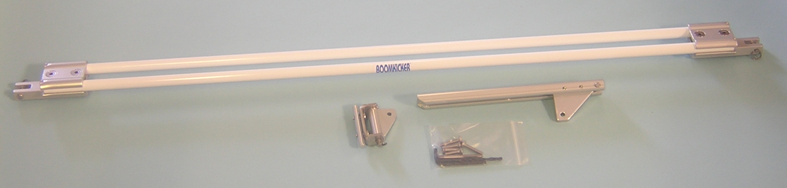
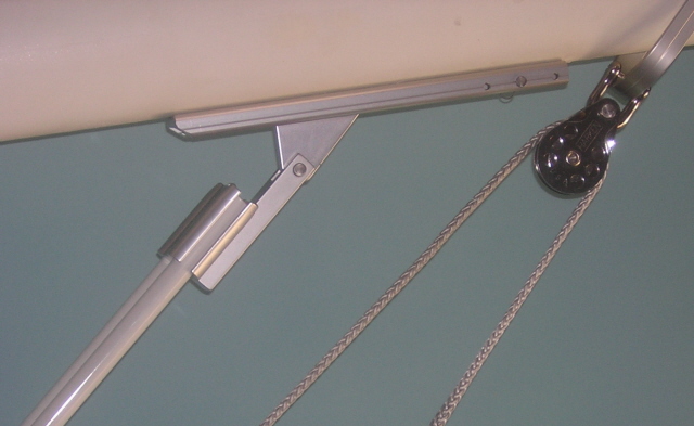
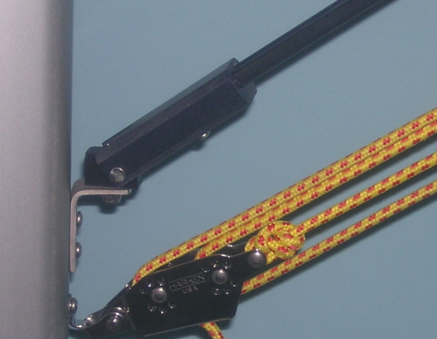
Boomkickers use two coated solid fiberglass spring rods to provide the force necessary to support the boom and mainsail. The rods are clamped into teflon coated, anodized aluminum end pieces and attached to universal mast and boom fittings. Fittings are included along with machine screw fasteners, the proper drill and tap and hex wrench. The mast fitting includes a round slide which, used in the luff groove, avoids drilling into the mast. Flat slides in varying widths are available from the factory. The slides can often be inserted at the sail opening above the gooseneck and slid down reassembling the fitting in position. If slides are not usable, the fitting can be attached directly to the mast using the same drill and tap provided for the boom. The custom extruded boom track is contoured to fit both round and flat bottom booms. The track has an adjustable clevis pin to set the maximum height the Boomkicker will lift the boom. The track length forward of the pin allows the boom to move higher if needed.
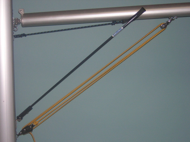
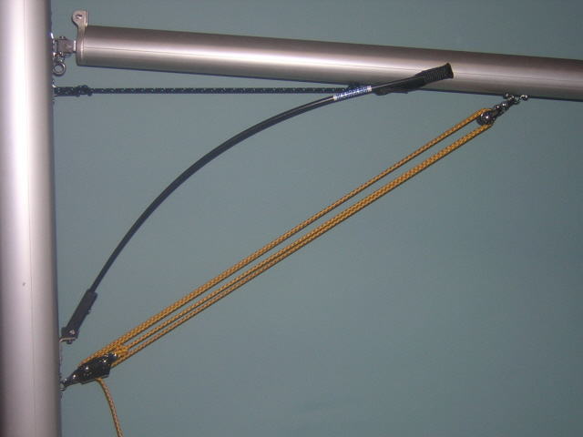
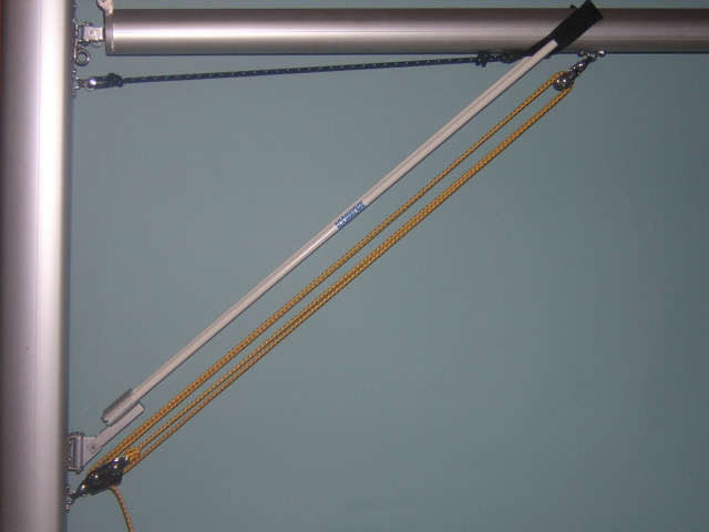
The pictures below show the basic set up of Boomkicker models 500, 750, 800, 1000, 1250 and 1500 with a multipurchase vang. Models 500 and 750 are identical except for rod diameter, the same goes for models 800 and 1000, and then models 1250 and 1500.
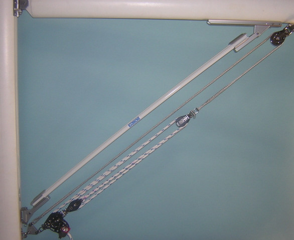  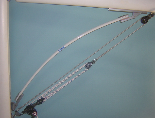
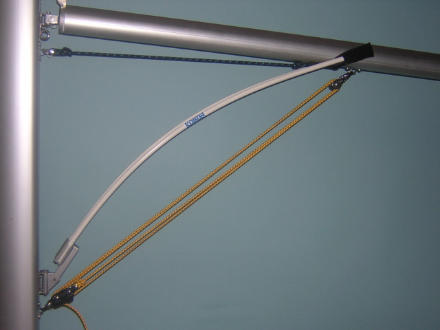
When installed, the Boomkicker is straight with the boom positioned above the usual sailing height. As the mainsheet or vang is tensioned, the Boomkicker flexes smoothly from straight to flexed. The force stays relatively constant as the Boomkicker continues to flex, which helps keep the vang efficient. Each model now includes only two rods of a specified diameter and force. If after installation the force is more or less then desired, optional rods are available either as exchange or for purchase. The more forceful the rods, the more support for the boom but the harder it will be to pull on the vang. In general only about 10 to 15 lbs should be needed to pull the end of the boom down by hand but it depends on your preference. Each 1/16" change in rod diameter equates to approximately 100lbs force at the Boomkicker or about 15 lbs. at the aft end of the boom. Using the boat list is a good way to see what has generally worked best for different boat designs. At their initial length, the rods provide as much as 6 feet of travel at the end of the boom depending on the set up. Within limits the spring rods can be shortened with a hacksaw to fit above the vang, with some loss of range.
The purpose and benefit of the track is to allow the Boomkicker to slide forward if the boom is allowed to raise beyond the Boomkickers' straight position or maximum travel. Sliding prevents the unit or fasteners from being overloaded in tension and used as a vang. Vang tension loads can be as much as 10 times the compression load the Boomkicker needs to support the boom.
BACK TO SPECS
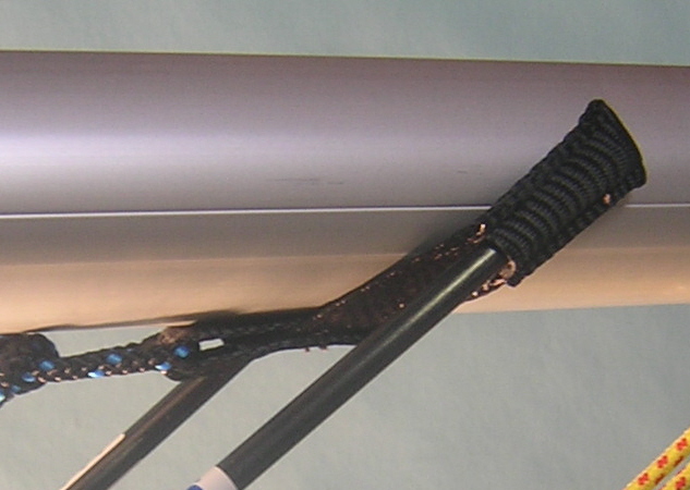
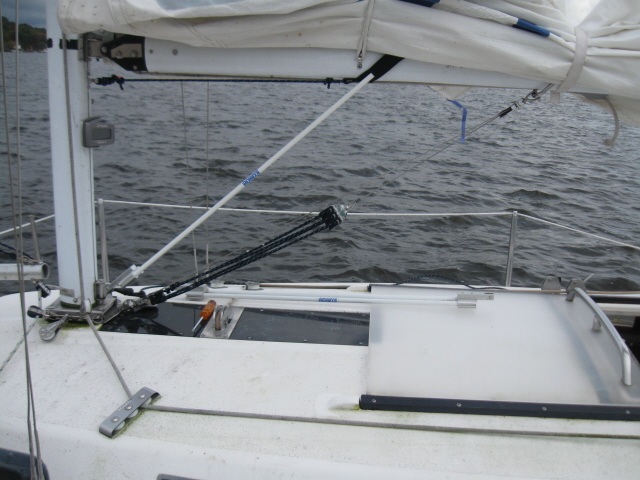
 The Boomkicker model K0312 works basically the same as the larger models by flexing as show below, but instead of attaching directly to the boom, a webbing sling, suspended between the two spring rods, supports the boom. Designed for smaller daysailers, these Boomkickers are easy to install with no drilling or tapping required. All parts fit in the luff groove of the mast. For trailering, the design makes rigging and de-rigging a snap, simply remove the boom and fold the Boomkicker up against the mast for storage. The Boomkicker model K0312 works basically the same as the larger models by flexing as show below, but instead of attaching directly to the boom, a webbing sling, suspended between the two spring rods, supports the boom. Designed for smaller daysailers, these Boomkickers are easy to install with no drilling or tapping required. All parts fit in the luff groove of the mast. For trailering, the design makes rigging and de-rigging a snap, simply remove the boom and fold the Boomkicker up against the mast for storage.
The sling, because it does not attach directly to the boom, allows these models to work with the simplest of goosenecks. Even if the boom just slides onto a pin at the gooseneck, or can roll, the Boomkicker can not push the boom back or restrict it from rolling around its central axis to follow the sail.
When installed, the Boomkicker is straight and the boom should be positioned above the usual sailing height. As the mainsheet or vang is tensioned, the Boomkicker flexes smoothly from straight to flexed. The force stays relatively constant as the Boomkicker continues to flex, which helps keep the vang efficient. Both the gooseneck eyestrap for the line and the mast fitting have standard a 3/8" diameter slide to fit in the luff groove and avoid drilling. 1/2" diameter is also available. The length of the line positions the sling along the boom and determines the initial boom height. The gooseneck eyestrap also serves as a stop if the gooseneck slides in the luff groove. Only one rod diameter is available for this model. In general only about 10lbs should be needed to pull the end of the boom down by hand. At their initial length, the rods provide as much as 6 feet of travel at the end of the boom depending on set up. If needed the spring rods can also be shortened within limits to fit above the vang with some loss of range.
Where both the K0312 and K0400 models have webbing slings, the mast end for the 312 is made of UHMW polyethylene, a stainless steel mast bracket and luff groove slides of teflon coated anodized aluminum. Sold since 1995, the design has proven simple and extremely durable.
BACK TO SPECS
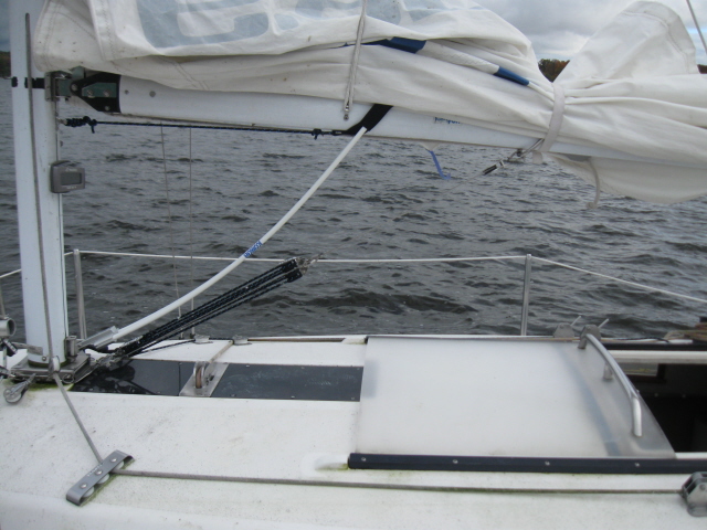
 The Boomkicker model K0400 works basically the same as the larger models by flexing as show below, but instead of attaching directly to the boom, a webbing sling, suspended between the two spring rods, supports the boom. Designed for smaller daysailers, these Boomkickers are easy to install with no drilling or tapping required. All parts fit in the luff groove of the mast. For trailering, the design makes rigging and de-rigging a snap, simply remove the boom and fold the Boomkicker up against the mast for storage. The Boomkicker model K0400 works basically the same as the larger models by flexing as show below, but instead of attaching directly to the boom, a webbing sling, suspended between the two spring rods, supports the boom. Designed for smaller daysailers, these Boomkickers are easy to install with no drilling or tapping required. All parts fit in the luff groove of the mast. For trailering, the design makes rigging and de-rigging a snap, simply remove the boom and fold the Boomkicker up against the mast for storage.
The sling, because it does not attach directly to the boom, allows these models to work with the simplest of goosenecks. Even if the boom just slides onto a pin at the gooseneck, or can roll, the Boomkicker can not push the boom back or restrict it from rolling around its central axis to follow the sail.
When installed, the Boomkicker is straight and the boom should be positioned above the usual sailing height. As the mainsheet or vang is tensioned, the Boomkicker flexes smoothly from straight to flexed. The force stays relatively constant as the Boomkicker continues to flex, which helps keep the vang efficient. Each model now includes only two rods of a specified diameter and force. If after installation the force is more or less then desired, optional rods are available either as exchange or for purchase. The more forceful the rods, the more support for the boom but the harder it will be to pull on the vang. In general only about 10lbs should be needed to pull the end of the boom down by hand. At their initial length, the rods provide as much as 6 feet of travel at the end of the boom depending on set up. If needed the spring rods can also be shortened within limits to fit above the vang with some loss of range.
Both the gooseneck eyestrap for the line and the mast fitting have standard 3/8" diameter slides to fit in the luff groove and avoid drilling. 1/2" diameter is also available. The length of the line positions the sling along the boom and determines the initial boom height. The gooseneck eyestrap also serves as a stop if the gooseneck slides in the luff groove.
Where both the K0312 and K0400 models have webbing slings, the model 400 mast end is all aluminum, basically the same one used on the model 500. Both models K0500 and K0400 share the same rod diameter and force, so the only difference or choice is whether you prefer the sling attachment or aluminum track fitting.
The K0400 can also be installed to flex down. It's highly recommended when the angle to the boom is lower then 40 degrees. As the rods flex down, the sling arms become more vertical, better capturing the boom.
BACK TO SPECS
|